
Flush Installation Sequence
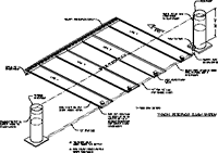
Lay out system on paper, determining location of reservoirs,
valves, and best routing of pipe.
Once
layout is ready, determine the needed materials and fittings. The
use of slip type fittings as much as possible is recommended.
With all piping, the manufacturer’s instructions must be
followed closely to ensure a long term, watertight seal.
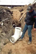
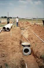
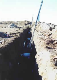
Lay all piping with risers at each valve location. Be sure all back
fill is properly placed and compacted to avoid future settlement.
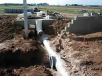
Bring fill up to mid-point of pipe.
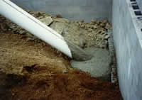
All fittings including elbows, tees, or other changes of direction
must now have concrete thrust blocks installed to insure stability
of pipe and prevent separation during operation.
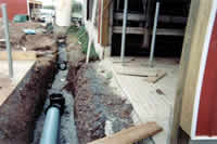
Complete the covering of pipe with compacted fill until there is
at least 12” of soil over the top of the pipe.
With 12” of cover, the trench should be thoroughly wetted
for at least 48 hours to further consolidate the soils.
Don’t forget to run any other conduits or lines required for
controls or other needs before trench is completely filled.
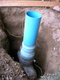
It is best to leave area at riser more open than remainder of pipe.
This provides space so risers can be cut down to proper height to
prepare for addition of flanges.
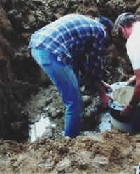
With riser at proper height, carefully glue flange to pipe. It is
best to have a preset laser level ready to verify proper height of
flange relative to floor during this process.
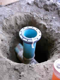
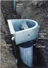
Riser with flange in place ready for final backfill. Don’t
forget to provide cable under valve if required.
With flange set, conduits run, and cable in place, this system is
ready for valve placement.
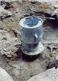
Remove lid from valves in preparation for installation of risers.
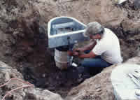
After bolting valve to flange, all reservoir type systems should
have a hold down cable installed to lessen pipe movement potential
in operation.
Complete valve ready for final backfill.
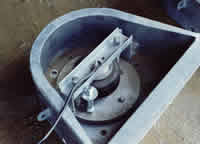
Round type valves install in similar manner to trapezoid type except
bolt flange is external.
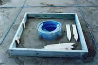
Back filled round valve being blocked out for concrete pour.
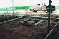
Installed valve blocked out ready for main floors to be poured.
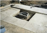
Floors have been poured with block out left for valve. Note curb/ramp
behind valve to control back splash. This is very important.
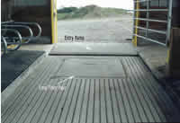
Final pour around valve. Again note entry ramp behind valve.
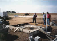
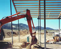
Preparing to pour reservoir footing/pad per drawing details. Note
tank weld plates pre-positioned to floor rebar mat.
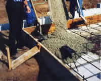
Pouring reservoir pad. Footing was poured prior to make positioning
plates easier.
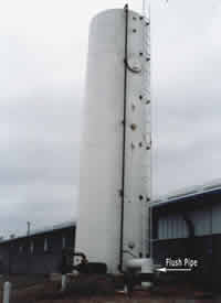
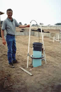
Installed reservoir. Note flush line exiting bottom of tank using
a through the side one-piece fixture from Agpro.
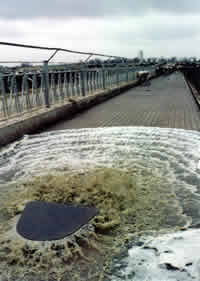
Once valves are connected to air and system is filled you are ready
to flush!